


Prepare the installation record
Identify the exact tracker model and hardware revision, obtain its current manual and agree the required signals with the vehicle owner. Record the intended mounting location, supply arrangement, SIM service and server destination. Keep real device identifiers and credentials in the project's controlled records, not in public photos or articles. Follow the vehicle manufacturer's requirements and use qualified personnel for electrical work.
Verify power before connecting
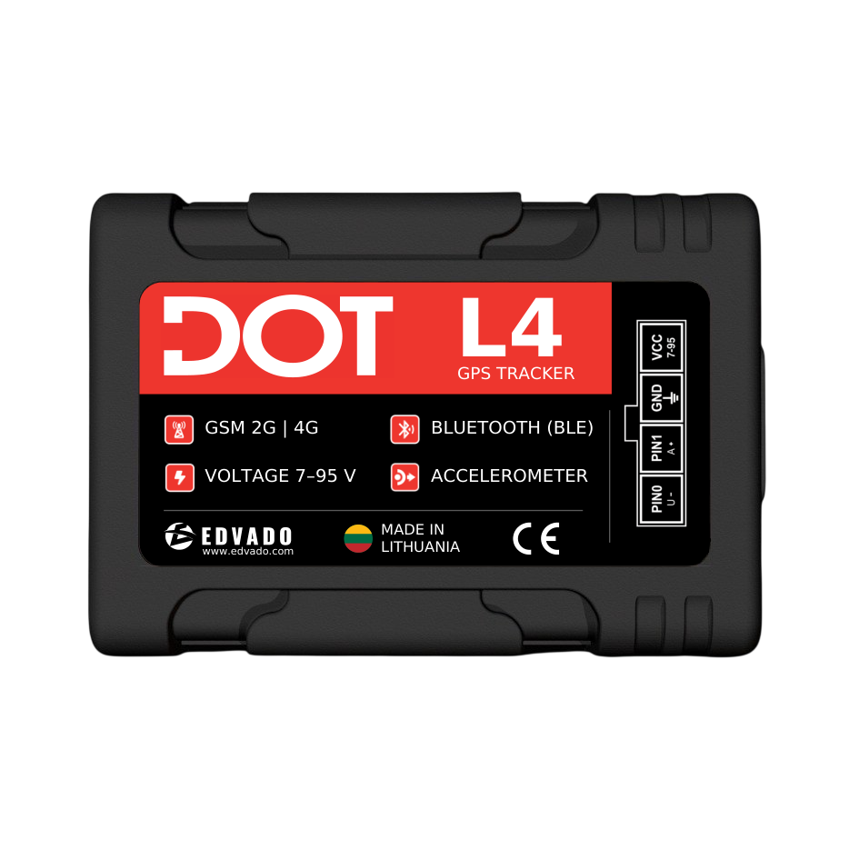
Use the pinout and protection specified for the actual device. Do not guess from wire colour or reuse another model's diagram. Check polarity, supply limits and grounding, including the conditions during starting and shutdown. The DOT L4 documentation lists a 7–95 V supply range; this does not remove the need for correct protection, wiring and transient assessment. Do not assume that every signal input accepts the supply voltage.
Choose a protected mounting location
Secure the tracker so it cannot move into pedals, steering mechanisms or airbag deployment areas. Protect wiring against sharp edges, heat and movement. Consider antenna orientation and obstruction by metal. DOT L4 has an IP54-rated housing according to its documentation: treat placement and connector protection accordingly rather than assuming unrestricted outdoor installation. Photograph the completed installation only when identifying and private details can be excluded.
Separate SIM setup from GNSS reception
An active SIM, correct APN and permitted data service are needed for network communication. Confirm roaming where relevant and enter the correct server address, port and protocol using the device instructions. A network connection does not establish a valid position fix; a position fix does not establish successful delivery. Check both independently. Never publish passwords, SIM identifiers or real server credentials in a support example.
Validate inputs and external sensors
Test ignition against the actual vehicle state, including parking and engine shutdown. For each external sensor, confirm electrical interface, format, identity and platform field. If using BLE, test reception with the vehicle in its normal closed condition. An RS485 or BLE label is not sufficient evidence of protocol compatibility. Do not connect to safety-critical vehicle circuits merely to obtain an additional data point.
Use an acceptance matrix
Before the road test, agree what counts as a pass. Record observed behaviour and timestamps for each item instead of writing only “working”. Test on an authorised route and have a passenger or stationary operator inspect the interface; the driver must not operate it while driving.
-
Parked vehicle: stable power, expected ignition state and a credible location.
-
Normal journey: position updates, correct timestamps and a recognisable route.
-
Planned stop: correct state transition without an artificial journey.
-
Controlled connection interruption: recovery checked against the model's documented buffering behaviour.
-
Required sensors: plausible values, units and visible update times.

Example: diagnose a missing journey
If the device has power but no journey appears, investigate the chain in order. Is a position available? Is mobile data connected? Is the server destination correct? Does the server accept and decode packets? Are timestamps and vehicle assignment correct in the platform? Changing several settings at once makes the result difficult to interpret. Use a short controlled test and retain redacted logs for Support rather than sending repeated commands blindly.
Complete the handover
Record the wiring revision, configuration version, test results and contact for support. Explain which settings may be changed and how updates will be reviewed. DOT Configurator provides a device-management entry point, while Locavist represents the monitoring layer; neither replaces vehicle-side acceptance testing. Use the DOT L4 manual and EDVADO Documentation Center for exact instructions. For a quotation, provide vehicle count, installation locations and required signals so that labour and accessories can be scoped correctly.