


EDVADO HARDWARE
DOT A2
2G tracker with BLE sensors and a wired fuel-level interface.
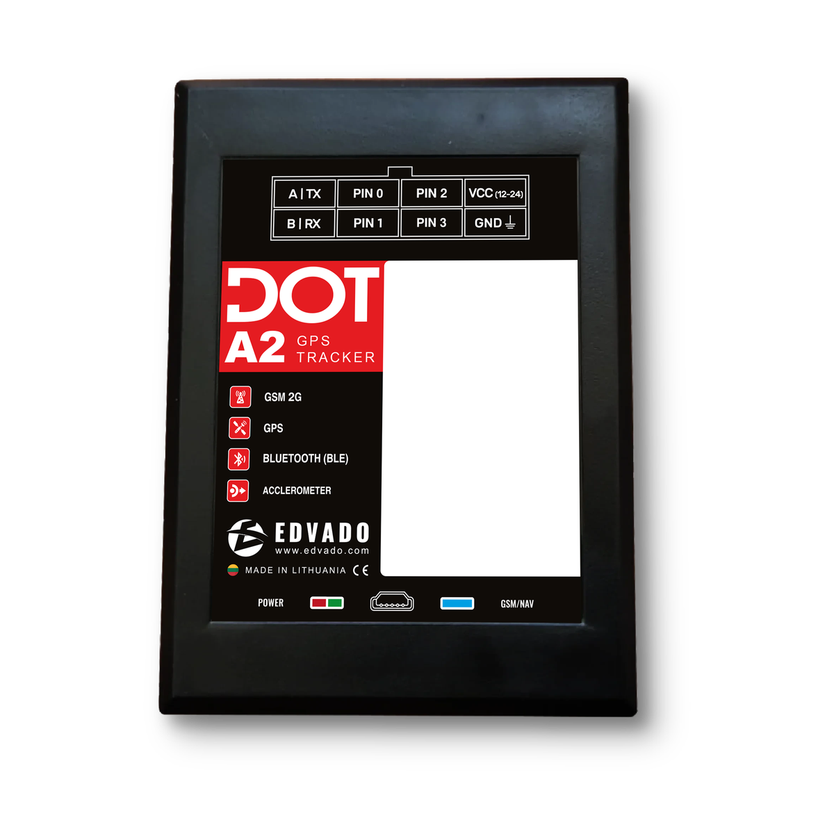
Description
DOT A2 monitors vehicles and stationary assets. It combines GPS/GLONASS positioning, 2G connectivity, an accelerometer and wired or wireless peripherals. The A-Series manual explicitly includes A2; A4 and A3-only features are not assigned to A2.
Specification information
Specifications are based on the available manufacturer manuals. Features not described in those documents are not confirmed.
Not specified: absent from sources. Not confirmed: catalog claim without a technical document. Not supported: explicitly excluded by the manufacturer.
Technical specifications
- Cellular networks
- 2G GSM / GPRS / EDGE · 850 / 900 / 1800 / 1900 MHz
- Supply voltage
- 8–50 V
- Reverse polarity protection
- Yes
- Dimensions
- 70 × 52–62 × 22 mm
- Weight (without wires and battery)
- 50 g
- Operating temperature (excluding battery)
- −40…+80 °C
- Enclosure protection
- IP54
- Navigation
- GPS / GLONASS
- Antennas
- Internal cellular, GNSS and Bluetooth
- SIM slots
- 1 × nano-SIM
- Bluetooth
- 4.0 LE
- RS485
- Omnicomm LLS · addresses 1 / 2 · polling 5 s
- RS232
- Optional
- USB
- Diagnostics and firmware updates
- Digital inputs
- 1 positive-trigger + 2 negative-trigger
- Low-side output
- 1 × open collector · up to 500 mA
- Non-volatile memory
- At least 12,000 events
- Motion sensor
- Built-in accelerometer
- Protocols
- INTERNAL / USER_AG / EGTS_ID / EGTS_IMEI
- Data transmission
- 2 servers simultaneously
Functions and installation
PIN0 supports digital, pulse and frequency modes; PIN2 supports ignition monitoring; PIN3 is a negative-trigger input. The open-collector PIN1 output switches to ground; use an external relay for loads exceeding 500 mA. Safe immobilization waits for a complete stop.
BLE peripherals are configured by MAC address: compatible fuel-level and temperature/contact sensors and DOT wireless relays. Wired LLS sensors use addresses 1 and 2. Wialon integration uses device type Arnavi and modem IMEI. Protocol and sensor configuration must match the installed equipment.
Connect permanent positive power last through a 1–2 A fuse near the vehicle connection point. Position the logo upwards without metal covering; for driving-behaviour monitoring, orient the main connector in the direction of travel. See the original manual for installation and configuration.
Source limitations
The manual gives 8–50 V as the working supply range; 12–24V is the connector marking, not a different specification. Dimensions exclude antennas and mounting hardware; the 52–62 mm width is a series range, not a precise A2 enclosure width.
The source contradicts itself on the positive-input threshold: Table 1 says less than 7 V, while the PIN2 section says above 7 V. Battery values are printed as 300–1200 mA, not mAh. No resolved input threshold or battery capacity is claimed; confirm both with the manufacturer.
This A-Series document does not establish equivalence between A4 and DOT A4 Wi-Fi; the dedicated A4 Wi-Fi documentation remains authoritative for that product.
DOT A-Series · EN · PDFDOT A2
Support
For installation and product questions, contact our technical support team.
Create a support request →